
A Combination of Gate Valves and Check Valves
The structure and characteristics of a multi-purpose valve combined with a steel gate valve and a check valve are analyzed, and the working principle of its operation without mutual interference is introduced.
1. Overview
Both gate valves and check valves are general-purpose valves for cut-off and circulation. The direction of movement of the closing part of the gate valve is perpendicular to that of the fluid, and it is operated by a driving device. It is a forced sealing valve. The disc of the check valve’s closing part automatically opens and closes by using the pressure difference between the front and back of the valve. Its function is to make the medium flow in one direction only and prevent it from flowing in the opposite direction. It is an automatic valve. This article introduces a check valve disc that is placed in the flow channel space on one side of the gate valve through structural design, so that the valve has a function of dual purposes.
2. Analysis of movement modes of valves
2.1. Gate valves
The flow channel of the gate valve body is straight-through, and the sealing surface of the valve plate with an angle of 5 matches the sealing surface of the valve seat in the valve body. The valve needs to drive the valve stem nut by driving the hand wheel or electric actuator to make the valve stem move up and down to control the opening and closing of the valve.
2.2. Swing check valves
The flow path of the swing check valve body is a straight-through type, and the sealing surface of the valve disc and the valve body has a certain slope to facilitate sealing. The check valve disc automatically opens or closes the valve depending on the pressure of the medium in the pipeline.
3. Analysis of the structure
The combined multi-purpose valve is composed of a gate valve and a check valve (Figure 1). The inner diameter of the flow channel hole of the valve body is the same as that of the pipe connected to the valve. The body part of the check valve is in the shape of a pipe, and the inner diameter of the flow channel shall be equal to the area of the flow channel (equal to the DN size of the gate valve) except for the maximum area of the check valve disc in the calculation of the designed gate valve, and close to the inner surface of the vertical flange. The direction terminates at the smallest diameter of the inner surface of the vertical flange.
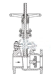
Figure 1 Combined multi-purpose valves
The inner wall of the check valve body is evenly distributed with guide ribs, and the guide ribs extend from the middle of the valve body to the flange end. The number of guide ribs can be set according to the size of the combined valve, but there are at least three to ensure that the outer circle of the large end of the check valve disc has a relatively stable coaxiality during movement. The end surface of the guide rib protruding to the middle of the valve body is vertically connected to the support ring rib plate at right angles, and is connected with the support ring to form a whole. The support ring is conducive to the bearing and positioning of the check disc shaft (Figure 2). The inner thread is machined at the flow channel opening of the check valve body, which cooperates with the outer thread of the check valve seat ring to form a thread pair.
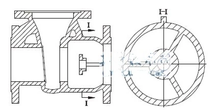
Figure 2 Valve bodies
4. Working principles
If the medium in the pipeline is not allowed to flow back during production, the fluid pressure on the inlet side (gate valve side) of the combined multi-purpose valve can push the check valve disc to move (Figure 3), and contact the check valve seat ring on the outlet side of the valve (Figure 4) the sealing surfaces and form a seal.
If the valve pressure is high, the gate valve can choose a design with a double angle of 5 to reduce the wear of the gate valve on the sealing surface of the valve body during operation under high pressure. If necessary, a buffer spring can be considered between the outer surface of the check valve disc and the collar to prevent the medium pressure in the pipeline from forming turbulent flow, causing vibration to hit the sealing surface of the check valve, generating noise or damaging the seal.
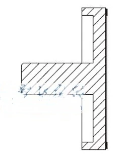
Figure 3 Check valve discs
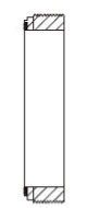
Figure 4 Seat rings of check valves
5. Conclusion
The design and manufacture of multi-purpose valves combined with gate valves and check valves are easy to implement, saves primary energy consumption, protects the environment, and reduces production costs.