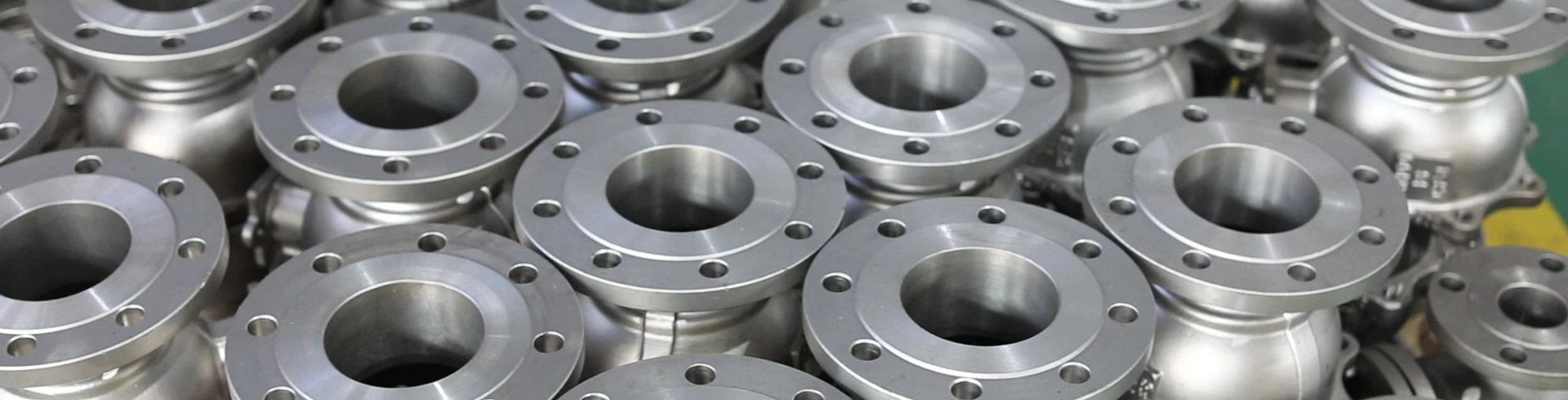
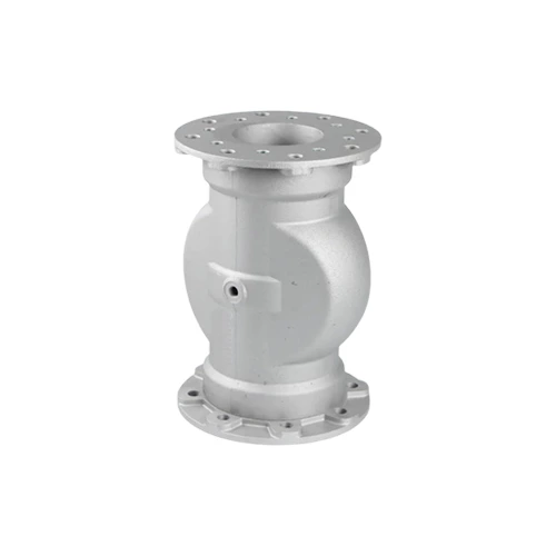
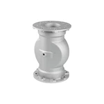
Pneumatic Aluminum Alloy Pinch Valve
- PN:
- 16~250
- DN:
- 15~1400
- Material:
- WCB, A105, LCC, LF2, 20ГЛ, 20ГМЛ, SS304, SS321, SS316, SS316Ti
- DRIVE:
- Manual, Electric, Pneumatic
- Connection:
- Flange, Welded, Threaded
- Medium:
- Water, steam, oil, chemical
Technical parameter
◆ nominal diameter: dn40-dn300
◆ working temperature: -
◆ working pressure: 2-6bar
◆ sealing grade: ANSI B 16-104, class
Product accessories
Solenoid valve, pressure switch, pressure regulator, safety protection device, filter, vacuum assembly, proportional regulating valve.
Jacket type
Wear resistant natural rubber, food safety natural rubber, high temperature resistant natural rubber, EPDM, black food safety natural rubber, light color food safety natural rubber, nitrile rubber, black food safety nitrile rubber, light color food safety nitrile rubber, fluororubber, silicone resin, neoprene, chlorosulfonated polyethylene rubber, butyl rubber and other materials.
Product advantages
◆ the most important advantages of pneumatic pinch valve are smooth medium flow, minimal friction resistance, 100% no leakage, no blockage and light weight.
◆ the shells of all flanged pinch valves are flat and oval, which ensures low compressed air consumption, which not only means energy saving, but also ensures the predetermined lip bending direction of pneumatic pinch valves.
◆ the predetermined lip bending direction can not only ensure 100% shut-off of medium flow, but also make it completely shut off even if there are large solid particles covered by the inner bushing.
Product use
Pneumatic pinch valve is used to shut off, regulate, quantify, wear, corrosive and fibrous media. For example, solutions for particles, powdery materials, pellets, dust, and liquids containing solids. The pinch valve is suitable for various pneumatic conveying systems. Its application fields include cement silo, pigment and particle treatment, ceramic, glass and plastic industry, sewage treatment, pharmaceutical industry, food industry and wine brewing industry.
Matters needing attention
◆ before replacing the inner bushing, cleaning the pinch valve or any other operation, be sure to turn off the air supply and disconnect the proximity air.
◆ when the pinch valve is running, make sure that the body parts, tools or other special bodies are in contact with it.
◆ understand and follow the instructions in the safety data sheet before the valve comes into contact with the conveying medium / product.
◆ when the conveying temperature of medium is high, do not touch the pinch valve (there is a risk of burning)
◆ it is only allowed to disassemble the pinch valve when the equipment has been shut down and is in a pressure free state.
◆ in order to prevent the maximum allowable working pressure / control pressure overload of the pinch valve, the equipment must be equipped with pressure limiter and safety valve.
◆ working medium is unstable and cannot be used as working medium.
◆ please note that the applied medium or the application environment of pinch valve may generate static electricity.
◆ when selecting pinch valve materials, not only the service life of the valve itself, but also the driving parts (gas circuit control, solenoid valve, etc.) shall be considered. Once the inner bushing is damaged, the medium may enter the control circuit.
Structural diagram
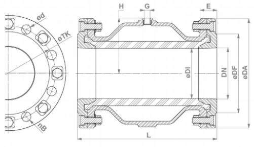
Main connection size and weight (mm)
| DN | DI | DA | DF | nB | d | TK | L | G | H | E | Weight (kg) | Volume (I) | max. (bar) | Thread | GT (mm) |
| 40 | 40 | 150 | 88 | 4 | 18 | 110 | 155 | G1/4" | 56 | 28 | 2,9 | 0, 20 | 6 | 1½" | 19 |
| 50 | 50 | 165 | 102 | 4 | 18 | 125 | 183 | G1/4" | 65 | 30 | 3,8 | 0, 30 | 6 | 2 | 24 |
| 65 | 65 | 185 | 122 | 4 | 18 | 145 | 183 | G1/4" | 81 | 28 | 4,3 | 0, 45 | 6 | 2½" | 22 |
| 80 | 80 | 200 | 138 | 8 | 18 | 160 | 228 | G1/4" | 95 | 31 | 5,6 | 0, 95 | 6 | 3 | 22 |
| 100 | 100 | 220 | 158 | 8 | 18 | 180 | 280 | G1/4" | 112 | 35 | 8,5 | 1, 70 | 6 | 4 | 20 |
| 125 | 118 | 250 | 184 | 8 | 18 | 210 | 348 | G1/4" | 136 | 40 | 12,1 | 3, 50 | 6 | / | / |
| 150 | 145 | 285 | 212 | 8 | 22 | 240 | 418 | G1/4" | 160 | 43 | 17,0 | 7, 00 | 6 | / | / |
| 200 | 190 | 340 | 268 | 8 | 22 | 295 | 558 | G3/8" | 206 | 60 | 33,2 | 15, 50 | 4 | / | / |
| 250 | 250 | 395 | 320 | 12 | 22 | 350 | 680 | G1/2" | 266 | 67 | 56,0 | 30, 00 | 3 | / | / |
| 300 | 300 | 445 | 370 | 12 | 22 | 400 | 820 | G1/2" | 306 | 70 | 86,0 | 49, 00 | 3 | / | / |
Related Products
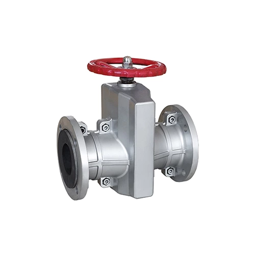
Manual Pinch Valve
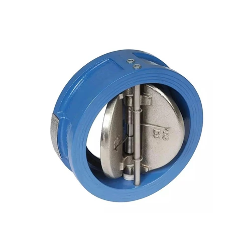
Wafer Dual Plate Check Valve
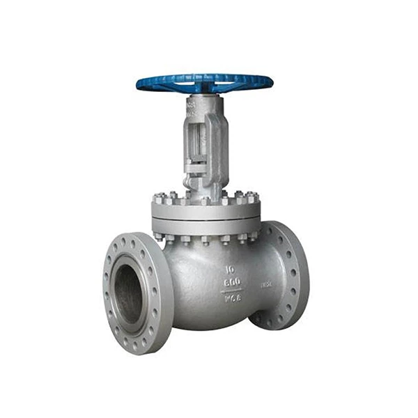
Cast steel Globe Valve
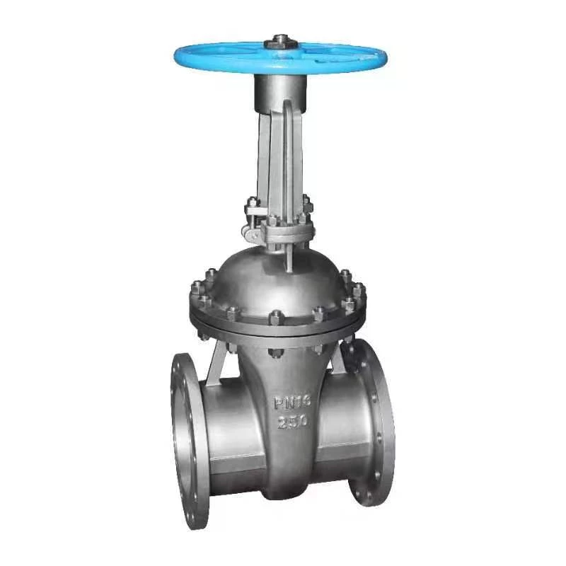
Cast steel Gate Valve
Get in Touch
Contact Us
325025,No. 588, Binhai Erdao 10th Road, Longwan District, Wenzhou City, Zhejiang Province